Table of Contents
Introduction to Geometries
Geometries are used to describe the geometrical properties of data objects in space and time. To use the geometry classes in the right way you have to understand the three different coordinate types present in MITK:
The different coordinate types
GeometryOverviewPage_WorldCoord
- World coordinates are describing the actual spatial position of all MITK objects regarding a global coordinate system, normally specified by the imaging modality
- World coordinates are represented by mitk::Point3D objects.
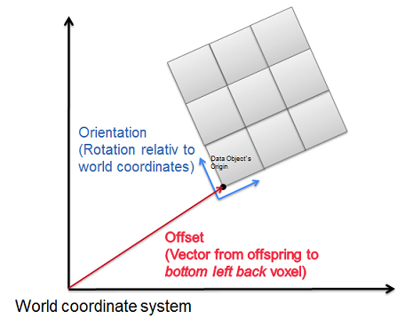
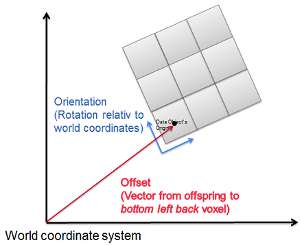
- The geometry defines the offset, orientation, and scale of the considered data objects in reference to the world coordinate systems.
- World coordinates are always measured in mm
- If you are dealing with an image geometry, the origin of an image is pointing to the CENTER of the bottom-left-back voxel.
- If you are NOT dealing with an image geometry (no defined discrete Voxels), the origin is pointing to the bottom-left-back CORNER
- Index coordinates can be converted to world coordinates by calling mitk::BaseGeometry::IndexToWorld()
Corner-based coordinates
Center-based image-coordinates
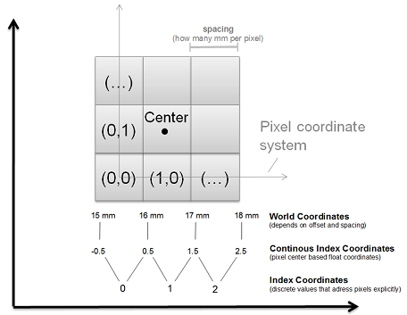
Continuous index coordinates
- Dividing world coordinates through the pixel spacing and simultaneously taking the offset into account leads to continuous index coordinates inside your dataobject. So continuous coordinates can be float values!
- Continuous index coordinates are represented by mitk::Point3D objects.
- They can be obtained by calling mitk::BaseGeometry::WorldToIndex(), where &pt_mm is a point in worldcoordinates.
Index coordinate system
- Index coordinates are discrete values that address voxels of a data object explicitly.
- Index coordinates are represented by itk::Index<3> objects.
- Basically they are continuous index coordinates which are rounded from half integer up.
- E.g. (0,0) specifies the very first pixel of a 2D image, (0,1) the pixel of the next column in the same row
- If you have world coordinates, they can be converted to discrete index coordinates by calling mitk::BaseGeometry::WorldToIndex()
Difference between Points and Vectors
Like ITK, MITK differentiate between points and vectors. A point defines a position in a coordinate system while a vector is the distance between two points. Therefore points and vectors behave different if a coordinate transformation is applied. An offset in a coordinate transformation will affect a transformed point but not a vector.
An Example:
If two systems are given, which differ by a offset of (1,0,0). The point A(2,2,2) in system one will correspond to point A'(3,2,2) in the second system. But a vector a(2,2,2) will correspond to the vector a'(2,2,2).
The Geometry Concept
As the superclass of all MITK geometries mitk::BaseGeometry holds:
- a spatial bounding box which is axes-parallel in index coordinates (often discrete indices of pixels), to be accessed by BaseGeometry::GetBoundingBox()
- a time related bounding box which holds the temporal validity of the considered data object in milliseconds (start and end time), to be accessed by BaseGeometry::GetTimeBounds(). The default for 3D geometries is minus infinity to plus infinity, meaning the object is always displayed independent of displayed time in MITK.
- position information in form of a Euclidean transform in respect to world coordinates (i.e. a linear transformation matrix and offset) to convert (discrete or continuous) index coordinates to world coordinates and vice versa, to be accessed by mitk::BaseGeometry::GetIndexToWorldTransform(). See also: Introduction to Geometries
- Many other properties (e.g. origin, extent, ...) which can be found in the mitk::BaseGeometry "class documentation"
- VERY IMPORTANT: A flag called
isImageGeometry, which indicates whether the coordinates are center-based or not! See also: Introduction to Geometries and Putting it together for an Image . IMPORTANT: Putting it together for an Image.
Every data object (sub-)class of BaseData has a mitk::TimeGeometry which is accessed by mitk::BaseData::GetTimeGeometry(). This mitk::TimeGeometry holds one or more mitk::BaseGeometry objects which describes the object at specific time points, e.g. provides conversion between world and index coordinates and contains bounding boxes covering the area in which the data are placed. There is the possibility of using different implementations of the abstract mitk::TimeGeometry class which may differ in how the time steps are saved and the times are calculated.
There are two ways to represent a time, either by a mitk::TimePointType or a mitk::TimeStepType. The first is similar to the continuous index coordinates and defines a Time Point in milliseconds from timepoint zero. The second type is similar to index coordinates. These are discrete values which specify the number of the current time step going from 0 to GetNumberOfTimeSteps(). The conversion between a time point and a time step is done by calling the method mitk::TimeGeometry::TimeStepToTimePoint() or mitk::TimeGeometry::TimePointToTimeStep(). Note that the duration of a time step may differ from object to object, so in general it is better to calculate the corresponding time steps by using time points. Also the distance of the time steps does not need to be equidistant over time, it depends on the used mitk::TimeGeometry implementation.
Each mitk::TimeGeometry has a bounding box covering the whole area in which the corresponding object is situated during all time steps. This bounding box may be accessed by calling mitk::TimeGeometry::GetBoundingBoxInWorld() and is always in world coordinates. The bounding box is calculated from all time steps, to manually start this calculation process call mitk::TimeGeometry::Update(). The bounding box is not updated if the getter is called.
The mitk::TimeGeometry does not provide a transformation of world coordinates into image coordinates since each time step may has a different transformation. If a conversion between image and world is needed, the mitk::BaseGeometry for a specific time step or time point must be fetched either by mitk::TimeGeometry::GetGeometryForTimeStep() or mitk::TimeGeometry::GetGeometryForTimePoint() and then the conversion is calculated by using this geometry.
The mitk::TimeGeometry class is an abstract class therefore it is not possible to instantiate it. Instead a derived class must be used. Currently the only class that can be chosen is mitk::ProportionalTimeGeometry which assumes that the time steps are ordered equidistant. To initialize an object with given geometries call mitk::ProportionalTimeGeometry::Initialize() with an existing BaseGeometry and the number of time steps. The given geometries will be copied and not referenced!
Also, the mitk::BaseGeometry is an abstract class and derived classes must be used. The most simple implementation, i.e. the one to one implementation of the BaseGeometry class, is the class mitk::Geometry3D.
mitk::SlicedGeometry3D is a sub-class of mitk::BaseGeometry, which describes data objects consisting of slices, e.g., objects of type Image (or mitk::SlicedData, which is the super-class of mitk::Image). Therefore, mitk::Image::GetTimeGeometry() will contain a list of mitk::SlicedGeometry3D instances. There is a special method mitk::SlicedData::GetSlicedGeometry(t) which directly returns a mitk::SlicedGeometry3D to avoid the need of casting.
The class mitk::SlicedGeometry3D contains a list of mitk::PlaneGeometry objects describing the slices in the image. We have here spatial steps from 0 to GetSlices(). mitk::SlicedGeometry3D::InitializeEvenlySpaced(PlaneGeometry *planeGeometry, unsigned int slices) initializes a stack of slices with the same thickness, one starting at the position where the previous one ends.
mitk::PlaneGeometry provides methods for working with 2D manifolds (i.e., simply spoken, an object that can be described using a 2D coordinate-system) in 3D space. For example it allows mapping of a 3D point on the 2D manifold using mitk::PlaneGeometry::Map().
Finally there is the mitk::AbstractTransformGeometry which describes a 2D manifold in 3D space, defined by a vtkAbstractTransform. It is a abstract superclass for arbitrary user defined geometries. An example is the mitk::ThinPlateSplineCurvedGeometry.
Putting it together for an Image
Please read this section carefully if you are working with Images!
The definition of the position of the corners of an image is different than the one of other data objects:
As mentioned in the previous section, world coordinates of data objects (e.g. surfaces) usually specify the bottom left back corner of an object.
In contrast to that, a geometry of an mitk::Image is center-based, which means that the world coordinates of a voxel belonging to an image points to the center of that voxel. E.g:
Center-based voxel
If the origin of e.g. a surface lies at (15,10,0) in world coordinates, the origin`s world coordinates for an image are internally calculated like the following:
If the image`s spacing is (x,y,z)=(1,1,3) then the corner coordinates are (14.5,9.5,-1.5).
If your geometry describes an image, the member variable isImageGeometry must be changed to true. This variable indicates also if your geometry is center-based or not.
The change can be done in two ways:
- You are sure that your origin is already center-based. Whether because you adjusted it manually or you copied it from another image. In that case, you can call the function
setImageGeometry(true)orimageGeometryOn()to set the bool variable to true. - You created a new geometry, did not manually adjust the origin to be center-based and have the bool value
isImageGeometryset to false (default). In that case, call the functionChangeImageGeometryConsideringOriginOffset(true). It will adjust your origin automatically and set the bool flag to true.
If you experience displaced contours, figures or other stuff, it is an indicator that you have not considered the origin offset mentioned above.
An image has a mitk::TimeGeometry, which contains one or more mitk::SlicedGeometry3D instances (one for each time step), all of which contain one or more instances of (sub-classes of) mitk::PlaneGeometry.
As a reminder: Geometry instances referring to images need a slightly different definition of corners, see mitk::BaseGeometry::SetImageGeometry. This is usually automatically called by Image.
Connection between MITK, ITK and VTK Geometries
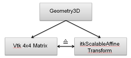
- VTK transformation for rendering
- ITK transformation for calculations
- Both automatically updated when one is changed
Attention: Not automatically updated when changed hardcoded. Example: geometry->GetVtkMatrix()->Rotate(...)