Medical Imaging Interaction Toolkit  2016.11.0
Medical Imaging Interaction Toolkit
MITK Tutorial - Step 4: Use several views to explore data

As in Step 2 and Step 3 one or more data sets may be loaded.

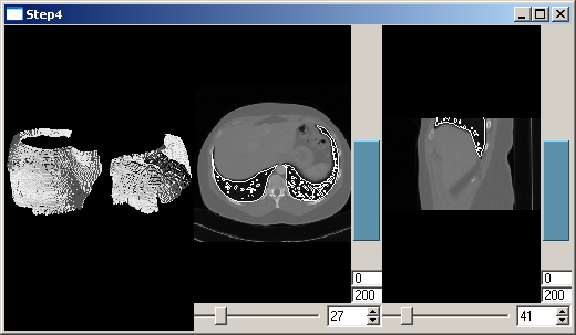
This now creates three views on the data. The QmitkRenderWindow is used for displaying a 3D view as in Step 3, but without volume-rendering. Furthermore two 2D views for slicing through the data are created. The class QmitkSliceWidget is used, which is based on the class QmitkRenderWindow, but additionally provides sliders to slice through the data. We create two instances of QmitkSliceWidget, one for axial and one for sagittal slicing. Step 4b enhances the program in that the two slices are also shown at their correct position in 3D as well as intersection-line, each in the other 2D view.

As in the previous steps, to obtain the result the program has to be executed using the image file Pic3D.nrrd and the surface file lungs.vtk.

Step 4a - Create axial and sagittal view

step4a_result.png

Create a Qt horizontal box for the layout:

#include <QHBoxLayout>

Then create a renderwindow:

//## The QmitkRenderWindow is used for displaying a 3D view as in Step3,
//## but without volume-rendering.
//## Furthermore, we create two 2D views for slicing through the data.
//## We use the class QmitkSliceWidget, which is based on the class
//## QmitkRenderWindow, but additionally provides sliders
//## to slice through the data. We create two instances of
//## QmitkSliceWidget, one for axial and one for sagittal slicing.
//## The two slices are also shown at their correct position in 3D as
//## well as intersection-line, each in the other 2D view.
int main(int argc, char *argv[])
{
QApplication qtapplication(argc, argv);
if (argc < 2)
{
fprintf(
stderr, "Usage: %s [filename1] [filename2] ...\n\n", itksys::SystemTools::GetFilenameName(argv[0]).c_str());
return 1;
}
// Register Qmitk-dependent global instances
//*************************************************************************
// Part I: Basic initialization
//*************************************************************************
// Create a DataStorage
//*************************************************************************
// Part II: Create some data by reading files
//*************************************************************************
int i;
for (i = 1; i < argc; ++i)
{
// For testing
if (strcmp(argv[i], "-testing") == 0)
continue;
//*********************************************************************
// Part III: Put the data into the datastorage
//*********************************************************************
// Load datanode (eg. many image formats, surface formats, etc.)
mitk::IOUtil::Load(argv[i], *ds);
}
//*************************************************************************
// Part IV: Create windows and pass the tree to it
//*************************************************************************
// Create toplevel widget with horizontal layout
QWidget toplevelWidget;
QHBoxLayout layout;
layout.setSpacing(2);
layout.setMargin(0);
toplevelWidget.setLayout(&layout);
//*************************************************************************
// Part IVa: 3D view
//*************************************************************************
// Create a renderwindow
QmitkRenderWindow renderWindow(&toplevelWidget);
layout.addWidget(&renderWindow);
// Tell the renderwindow which (part of) the datastorage to render
renderWindow.GetRenderer()->SetDataStorage(ds);
// Use it as a 3D view

Create a 2D view for slicing axially:

QmitkSliceWidget view2(&toplevelWidget);
layout.addWidget(&view2);
view2.SetLevelWindowEnabled(true);
// Tell the QmitkSliceWidget which (part of) the tree to render.
// By default, it slices the data axially
view2.SetDataStorage(ds);

Then create a 2D view for slicing sagitally.

QmitkSliceWidget view3(&toplevelWidget);
layout.addWidget(&view3);
view3.SetDataStorage(ds);

The toplevelWidget is now the new main widget:

return qtapplication.exec();

Step 4b - Display slice positions

step4b_result.png

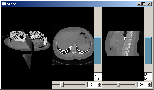
We now want to see the position of the slice in 2D and the slice itself in 3D. Therefore it has to be added to the tree:

ds->Add(view2.GetRenderer()->GetCurrentWorldGeometry2DNode());
ds->Add(view3.GetRenderer()->GetCurrentWorldGeometry2DNode());

Slice positions are now displayed as shown in the picture.

[Previous step] [Next step] [Main tutorial page]