Table of Contents
Introduction
This view is in development to offer the user a way to visualize MatchPoint registrations (so the transformation/deformation field they represent) in a MITK scene. Currently, a simple grid visualization and glyph visualization is implemented.
- Remarks
- This is an experimental version and work in progress. So please excuse errors or usage issues and report them at https://phabricator.mitk.org.
Usage

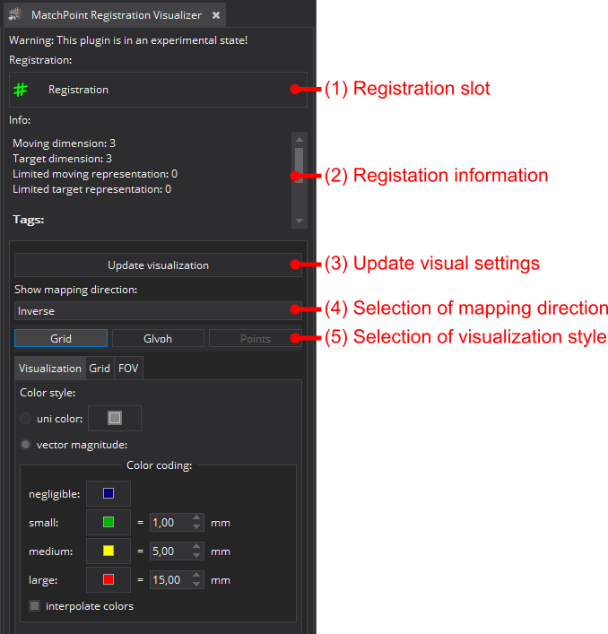
The view has following steps/sections:
(1) Registration slot: Shows the currently selected registration which is visualized and whose visualization settings should be altered. Click to change.
(2) Registration information: General information on the selected registration.
(3) Update visual settings: By clicking the button the current settings will be accepted and the visualization of the registration will be updated accordingly.
(4) Mapping direction: Allows to select the mapping direction that should be visualized (more details see below Information regarding the directions).
(5) Visualization style: Select how the registration should be visualized. Currently two options are available.:
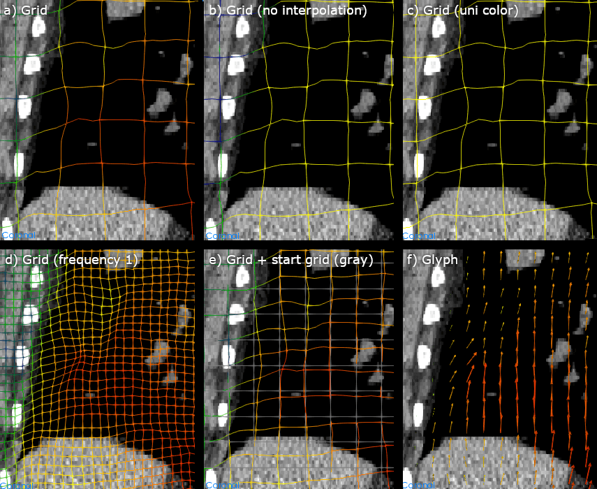
- Grid: Visualize as a wire frame grid that is deformed by the registration. The magnitude of deformation can be encoded in the grid color (cf style example "a)" below).
- Glyph: Visualize as a cloud of arrows that follow the deformation vectors of the registrations. The magnitude of deformation can be encoded in the glyph color (cf style example "f)" below).
More details can be found in the settings and style section below.

Visualization settings

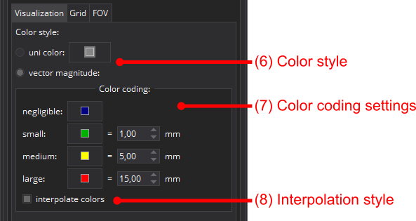
(6) Color style: The following color styles are available:
- uni color: everything painted in the selected color (cf style example "c)"). Click on the color button to change the used color.
- vector magnitode: the color is depending on the respective vector magnitude of the deformation field (cf style example "a)" and "b)"). See (7) for instructions to change the used color encoding for the magnitude.
(7) Color coding settings: One can change the color and associated vector length (in mm) for 4 classes of magnitude (negligible, small, medium and large). The color is encoded accordingly.
(8) Interpolate colors: By default activated, the colors between to magnitude classes (see (7)) will be linear interpolated (e.g. with the settings given in the example shifts of 5 mm will be yellow, 10 mm will be orange and >=15 mm will be red). If interpolation is deactivated the color of one class is used till a next higher class is reached. Cf style example "a)" and "b)", in "b)" no red color can be seen because no shift was 15 mm or greater (magnitude class "large").
Grid settings

These are only available for style "grid".
(9) Grid frequency: Allows to control how spares the grid frame should be. With a frequency n only each n-th element of the frame will be visualized, so the visual grid has n-times the spacing of the FOV. One can also achieve something similar with just changing the FOV spacing (see below), but using the frequency allows for a sparse frame and still having a high resolution in the frame deformation. The latter one would loose if just using a low FOV spacing. Style example "a)" and "d)" illustrate different frequency settings and there effect.
(10) Start grid: If activated also the start grid of the registration will (for the chosen direction) will be visible. This is another grid specific possibility to illustrate the amount of deformation (cf style example "e)").
(11) Start grid color: Select the color that should be used for the start grid. Click on the color button to change the used color.
Field of view (FOV) settings

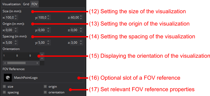
The field of view defines the area of space (grid) that should be used for the visualization of the registration.
(12) Size: Size of the FOV in mm.
(13) Origin: Origin of the FOV in mm.
(14) Spacing: Spacing of the FOV in mm. This directly impact the visualization's level of detail. IMPORTANT: Please be careful with setting small spacings, as it can lead to computational very expensive visualizations.
(15) Orientation: Orientation matrix of the FOV (only readable).
(16) FOV Reference slot: Select an image that should be used to define the geometric properties of the FOV. By default (and available) the target image used to determine the registration will be used. Click slot to change the FOV reference.
(17) Relevant FOV reference properties: One can select which properties of the reference image will be used to specify the FOV.
Information regarding the directions
Registrations can have two supported directions (direct and inverse). The direct kernel maps from the moving space into the target space, so this is the direction that "naively" people assume when they think about registrations. But practically it is only used to map continuous data like point sets. The inverse kernel maps from the target space into the moving space and is used to map images by so called inverse mapping. The effect is most obvious in the glyph style, where the glyphs points from the mapped space to the point in the moving space.
Data reference
The data visible in the visualization styles images is part of the Patient 1 of the DIR_validation_data data set. For further information: https://www.creatis.insa-lyon.fr/rio/dir_validation_data
By downloading this data, you agreeing to follow these guidelines. When using any of the data provided for publications, please make reference to:

The institution from which they were obtained: the Léon Bérard Cancer Center & CREATIS lab, Lyon, France.
The article containing the description of this data:

J. Vandemeulebroucke, S. Rit, J. Kybic, P. Clarysse, and D. Sarrut. Spatiotemporal motion estimation for respiratory-correlated imaging of the lungs. In Med Phys, 2011, 38(1), 166-178. pdf
