Medical Imaging Interaction Toolkit  2016.11.0
Medical Imaging Interaction Toolkit
The MITK-IGT Tutorial View

This view is not meant as an end-user module. It contains tutorial program code that explains how to use the MITK-IGT component.

It contains only two buttons. The "Start image guided therapy" button will create a virtual tracking device and a virtual tool. It will move the tool around on random paths in a tracking volume of 200x200x200 mm. The tool is visualized with a cone. If you do not see a cone moving around, you will need to initialize the rendering views correctly. Use the DataManager view to perform a global reinit.

The symbol of this view is the following:

icon_igt_simple_example.png

and the whole view looks like this:

IGTExampleIGT_QT_Tutorial_PluginView.png

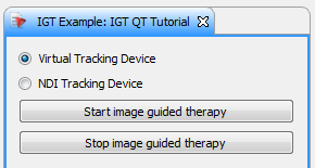
In this tutorial we connect to the NDI Polaris tracking system (or alternatively use a virtual tracking device) and we will show the movement of a tool as cone in the StdMultiWidget editor.

First of all, you will have to add an IGT dependency to your cmake list. For this example, MitkIGTUI would be sufficient, but as the plugin contains several views, we have additional OpenIGTLink and US dependencies:

project(org_mitk_gui_qt_igtexamples)
EXPORT_DIRECTIVE IGTEXAMPLES_EXPORT
EXPORTED_INCLUDE_SUFFIXES src
MODULE_DEPENDS MitkQtWidgetsExt MitkIGT MitkIGTUI MitkOpenIGTLink MitkOpenIGTLinkUI MitkUS
)

More information on how to create your own plugin can be found here: How to create a new MITK Plugin

When clicking the start button, a cone should move in the 3D view and stop after clicking the stop button.

The view has several fuctions. Most of them deal with the basic functionality with the plugin (e.g. CreateQTPartControl or CreateConnections). For a deeper understanding, you might have a look at the files QmitkIGTTutorialView.cpp and QmitkIGTTutorialView.h For our IGT functionality, the following functions are important:

  • OnStartIGT: Starts the navigation pipeline
  • OnStopIGT: Disconnect the pipeline
  • OnTimer: Updates the view

Let's now have a deeper look at these functions.

OnStartIGT

void QmitkIGTTutorialView::OnStartIGT()
{
//This method is called when the "Start Image Guided Therapy" button is pressed. Any kind of navigation application will
//start with the connection to a tracking system and as we do image guided procedures we want to show
//something on the screen. In this tutorial we connect to the NDI Polaris tracking system pr a virtual tracking device and we will
//show the movement of a tool as cone in MITK.

We first check in a try environment, if we should use an NDI tracking device or a virtual device. Let's start with NDI, we hardcode the parameters here and give out a warning. In your propper application, the parameters should be set via the gui aswell (see The MITK-IGT Tracking Toolbox ), but for simplicity, we just set hardcoded parameters here. If you want to try it with your own NDI device, you need to adapt these parameters here in the code:

try
{
if(m_Controls->m_NDITrackingRadioButton->isChecked())
{
/**************** Variant 1: Use a NDI Polaris Tracking Device ****************/
//Here we want to use the NDI Polaris tracking device. Therefore we instantiate a object of the class
//NDITrackingDevice and make some settings which are necessary for a proper connection to the device.
MITK_INFO << "NDI tracking";
QMessageBox::warning ( NULL, "Warning", "You have to set the parameters for the NDITracking device inside the code (QmitkIGTTutorialView::OnStartIGT()) before you can use it.");
tracker->SetPortNumber(mitk::SerialCommunication::COM4); //set the comport
tracker->SetBaudRate(mitk::SerialCommunication::BaudRate115200); //set the baud rate
tracker->SetType(mitk::NDIPolarisTypeInformation::GetTrackingDeviceName()); //set the type there you can choose between Polaris and Aurora
//The tools represent the sensors of the tracking device. In this case we have one pointer tool.
//The TrackingDevice object it self fills the tool with data. So we have to add the tool to the
//TrackingDevice object.
// The Polaris system needs a ".rom" file which describes the geometry of the markers related to the tool tip.
//NDI provides an own software (NDI architect) to generate those files.
tracker->AddTool("MyInstrument", "c:\\myinstrument.rom");

The tracking device has to be set to a source. For more information on the tracking pipeline, please have a look at the IGT filter pipeline.

//The tracking device object is used for the physical connection to the device. To use the
//data inside of our tracking pipeline we need a source. This source encapsulate the tracking device
//and provides objects of the type mitk::NavigationData as output. The NavigationData objects stores
//position, orientation, if the data is valid or not and special error informations in a covariance
//matrix.
//
//Typically the start of a pipeline is a TrackingDeviceSource. To work correct we have to set a
//TrackingDevice object. Attention you have to set the tools before you set the whole TrackingDevice
//object to the TrackingDeviceSource because the source need to know how many outputs should be
//generated.
m_Source = mitk::TrackingDeviceSource::New(); //We need the filter objects to stay alive,
//therefore they must be members.
m_Source->SetTrackingDevice(tracker); //Here we set the tracking device to the source of the pipeline.

Alternatively, we can setup a virtual tracking device. We create this device, set the bounds, add a tool and connect it to the source:

else
{
/**************** Variant 2: Emulate a Tracking Device with mitk::VirtualTrackingDevice ****************/
// For tests, it is useful to simulate a tracking device in software. This is what mitk::VirtualTrackingDevice does.
// It will produce random position, orientation and error values for each tool that is added.
MITK_INFO << "virtual tracking"<<endl;
mitk::ScalarType bounds[] = {0.0, 200.0, 0.0, 200.0, 0.0, 200.0};
tracker->SetBounds(bounds);
tracker->AddTool("MyInstrument"); // add a tool to tracker
//The tracking device object is used for the physical connection to the device. To use the
//data inside of our tracking pipeline we need a source. This source encapsulate the tracking device
//and provides objects of the type mitk::NavigationData as output. The NavigationData objects stores
//position, orientation, if the data is valid or not and special error informations in a covariance
//matrix.
//
//Typically the start of a pipeline is a TrackingDeviceSource. To work correct we have to set a
//TrackingDevice object. Attention you have to set the tools before you set the whole TrackingDevice
//object to the TrackingDeviceSource because the source need to know how many outputs should be
//generated.
m_Source = mitk::TrackingDeviceSource::New(); //We need the filter objects to stay alive,
//therefore they must be members.
m_Source->SetTrackingDevice(tracker); //Here we set the tracking device to the source of the pipeline.
/**************** End of Variant 2 ****************/
}

Now we need to connect the tracking system

m_Source->Connect(); //Now we connect to the tracking system.
//Note we do not call this on the TrackingDevice object

For the visualisation, we need an object. Here, we create a red cone

//As we wish to visualize our tool we need to have a PolyData which shows us the movement of our tool.
//Here we take a cone shaped PolyData. In MITK you have to add the PolyData as a node into the DataStorage
//to show it inside of the rendering windows. After that you can change the properties of the cone
//to manipulate rendering, e.g. the position and orientation as in our case.
mitk::Cone::Pointer cone = mitk::Cone::New(); //instantiate a new cone
double scale[] = {10.0, 10.0, 10.0};
cone->GetGeometry()->SetSpacing(scale); //scale it a little that so we can see something
mitk::DataNode::Pointer node = mitk::DataNode::New(); //generate a new node to store the cone into
//the DataStorage.
node->SetData(cone); //The data of that node is our cone.
node->SetName("My tracked object"); //The node has additional properties like a name
node->SetColor(1.0, 0.0, 0.0); //or the color. Here we make it red.
this->GetDataStorage()->Add(node); //After adding the Node with the cone in it to the
//DataStorage, MITK will show the cone in the
//render windows.

The visualization filter will actually render the cone

//For updating the render windows we use another filter of the MITK-IGT pipeline concept. The
//NavigationDataObjectVisualizationFilter needs as input a NavigationData and a
//PolyData. In our case the input is the source and the PolyData our cone.
//First we create a new filter for the visualization update.
m_Visualizer->SetInput(0, m_Source->GetOutput()); //Then we connect to the pipeline.
m_Visualizer->SetRepresentationObject(0, cone); //After that we have to assign the cone to the input
//Now this simple pipeline is ready, so we can start the tracking. Here again: We do not call the
//StartTracking method from the tracker object itself. Instead we call this method from our source.
m_Source->StartTracking();

For a continuous display, we need to call update, here we decide to do it every 100 ms using a timer.

//Now every call of m_Visualizer->Update() will show us the cone at the position and orientation
//given from the tracking device.
//We use a QTimer object to call this Update() method in a fixed interval.
if (m_Timer == NULL)
{
m_Timer = new QTimer(this); //create a new timer
}
connect(m_Timer, SIGNAL(timeout()), this, SLOT(OnTimer())); //connect the timer to the method OnTimer()
m_Timer->start(100); //Every 100ms the method OnTimer() is called. -> 10fps

Disable the selection of tracking devices during tracking:

//disable the tracking device selection
this->m_Controls->m_NDITrackingRadioButton->setDisabled(true);
this->m_Controls->m_virtualTrackingRadioButton->setDisabled(true);

For propper coding, you should always catch the exceptions:

catch (std::exception& e)
{
// add cleanup
MITK_INFO << "Error in QmitkIGTTutorial::OnStartIGT():" << e.what();
}

OnTimer

Each time, the timer is updated, the following code is executed:

void QmitkIGTTutorialView::OnTimer()
{
//Here we call the Update() method from the Visualization Filter. Internally the filter checks if
//new NavigationData is available. If we have a new NavigationData the cone position and orientation
//will be adapted.
m_Visualizer->Update();
mitk::TimeGeometry::Pointer geo = this->GetDataStorage()->ComputeBoundingGeometry3D(this->GetDataStorage()->GetAll());
this->RequestRenderWindowUpdate();
}

OnStopIGT

This function will stop the pipeline and clean up everything:

void QmitkIGTTutorialView::OnStopIGT()
{
//This method is called when the Stop button is pressed. Here we disconnect the pipeline.
if (m_Timer == NULL)
{
MITK_INFO << "No Timer was set yet!";
return;
}
//To disconnect the pipeline in a save way we first stop the timer than we disconnect the tracking device.
//After that we destroy all filters with changing them to NULL.
m_Timer->stop();
disconnect(m_Timer, SIGNAL(timeout()), this, SLOT(OnTimer()));
m_Timer = NULL;
m_Source->StopTracking();
m_Source->Disconnect();
m_Source = NULL;
m_Visualizer = NULL;
m_Source = NULL;
this->GetDataStorage()->Remove(this->GetDataStorage()->GetNamedNode("My tracked object"));
//enable the tracking device selection
this->m_Controls->m_NDITrackingRadioButton->setEnabled(true);
this->m_Controls->m_virtualTrackingRadioButton->setEnabled(true);
}

You now have a very simple plugin, which creates an own tracking device and starts or stops tracking. Of course, for your more advanced project, you could implement a new tracking device to be available in every plugin (see How To Implement A Tracking Device) or use already implemented tracking devices via the tracking toolbox and/or microservices. This small example should just show you the most simple way to start tracking.

Return to the [IGT Tutorial Overview]