|
Medical Imaging Interaction Toolkit
2016.11.0
Medical Imaging Interaction Toolkit
|
|
Medical Imaging Interaction Toolkit
2016.11.0
Medical Imaging Interaction Toolkit
|
The Measurement view enables the user to interact with 2D images or single slices of 3D image stacks and planar figure data types. It allows to measure distances, angels, pathes and several geometric figures on a dataset.
The workflow to use this view is:

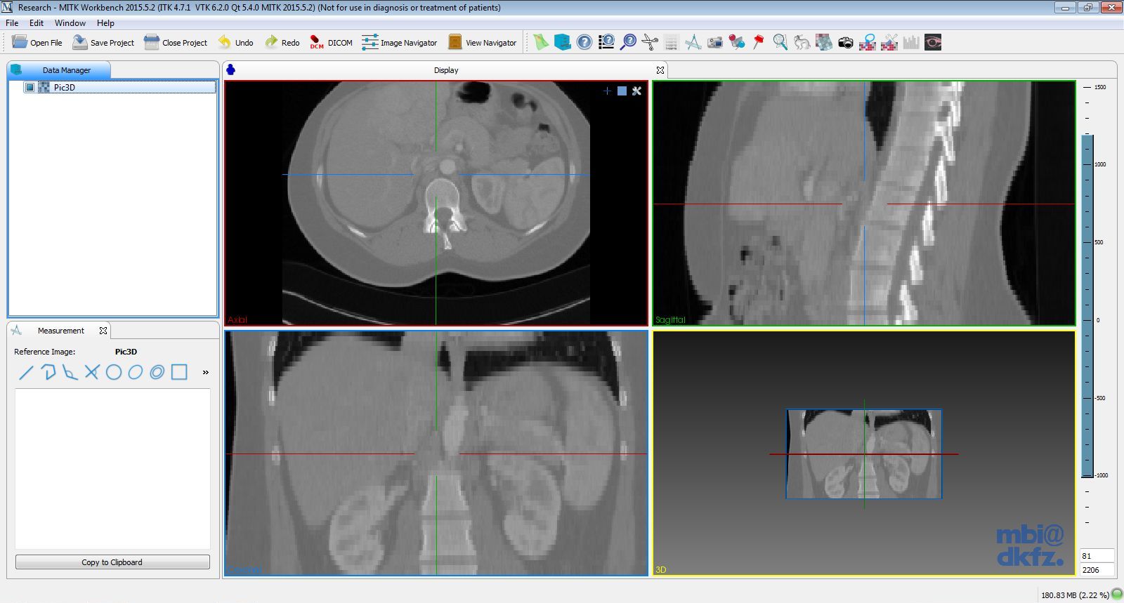
The workflow is repeatedly useable with the same or different measurement figures, which are correlated to the choosen image and can be saved together with it for future use. On pressing the Measurement icon (see picture below the page title) in the view button line the basic appearance of the view is as follws.

The standard working plane is "Axial" but the other standard viewplanes ("Saggital" and "Coronal") are also valid for measurements. To swap between the view planes refer to the application user manual.
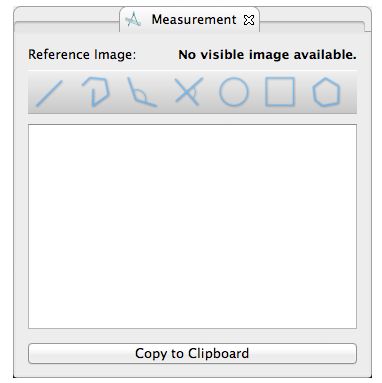
The view as it is depicted below offers the following features in the order of apperance on the image from top to bottom:

The first information is the selected image's name (here: DICOM-MRI-Image) followed by the measurement figures button line with the seven measurement figures. From left to right the buttons are connected with the following functions:
Draws a line between two set points and returns the distance between these points.
Draws a path between several set points (two and more) and calculates the circumference, that is all line's length summed up. Add the final point by double left click.
Draws two lines from three set points connected in the second set point and returns the inner angle at the second point.
Draws two lines that may but must not intersect from four set points. The returned angle is the one depicted in the icon.
Draws a circle by setting two points, whereas the first set point is the center and the second the radius of the circle. The measured values are the radius and the included area.
Draws a rectangle by setting two points at the opposing edges of the rectangle starting with the upper left edge. The measured values are the circumference and the included area.
Draws a polygon by setting three or more points. The measured values are the circumference and the included area. Add the final point by double left click.
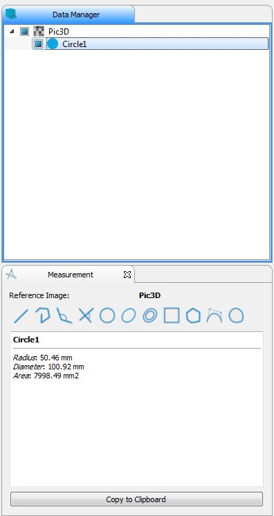
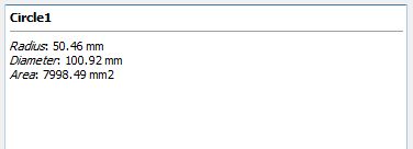
Below the buttonline the statistics window is situated, it displays the results of the actual measurements from the selected measurement figures. The content of the statistics window can be copied to the clipboard with the correspondig button for further use in a table calculation programm (e.g. Open Office Calc etc.).

The last row contains again a button line to swap from the measurement perspective (activated in the image) to other supported MITK perspectives.
This Section is subdivided into four subsections:
Let's start with subsection 1
There are two possible ways to add an image to the programm. One is to grap the image with left mouse click from your prefered file browser and simply drag&drop it to the View Plane field. The other way is to use the

The wanted image appears in the View Plane and in the Data Manager the images name appears as a new tree node. Now the image is loaded it can be adjusted in the usual way ( zoom in/out: right mouse button + moving the mouse up and down, moving the image: press mouse wheel and move the mouse to the wished direction, scroll through the slices( only on 3D images): scroll mouse wheel up and down).

After the image is loaded the image's name appears in the Data Manager. By left-clicking on the image name the buttonline becomes activated.
The measurement view comes with seven measurement figures(see picture below), that can be applied to the images.

The results of the measurement with each of these figures is shown in the statistics window and in the lower right corner of the view plane.

When applying more then one measurement figure to the image the actual measurement figure is depicted in red and the displayed values belong to this measurement figure. All measurement figures become part of the Data Manager as a node of the image tree.
After applying the wanted measurement figures the entire scene consisting of the image and the measurement figures can be saved for future use. Therefore just click the right mouse button when over the image item in the Data Manager and choose the item "Save" in the opening item list. Following to that a save dialog appears where the path to the save folder can be set. Afterwards just accept your choice with the save button.
If the single measurement figures or the image is not needed any longer, it can be removed solely or as an entire group. The image can't be removed without simultaneously removing all the dependent measurement figures that belong to the image tree in the Data Manager. To remove just select the wanted items in the data manager list by left-click on it or if several items wanted to be removed left click on all wanted by simultaneously holding the ctrl-button pressed.
For more detailed usage of the save/remove functionality refer to the Data Manager User Manual.
" \_linebr \image latex QmitkMeasurementToolbox_MeasurementGUI.png "Graphical User Interface of Measurement –>" width=16.00cm